Post Filters

We recently headed out to Palo Duro canyon for a few days of tent camping in the cold, coyote-infested wilderness. I thought perhaps it might be a little hard to get our phone batteries to last the duration of the trip. Luckily, I had some random leftover parts laying around from various dumpster dives and such, and ended up having everything I needed to build the circuit! The whole thing required pretty minimal soldering, which would be nice if I wasn’t itching to use the Weller (!) I got as a Christmas gift.
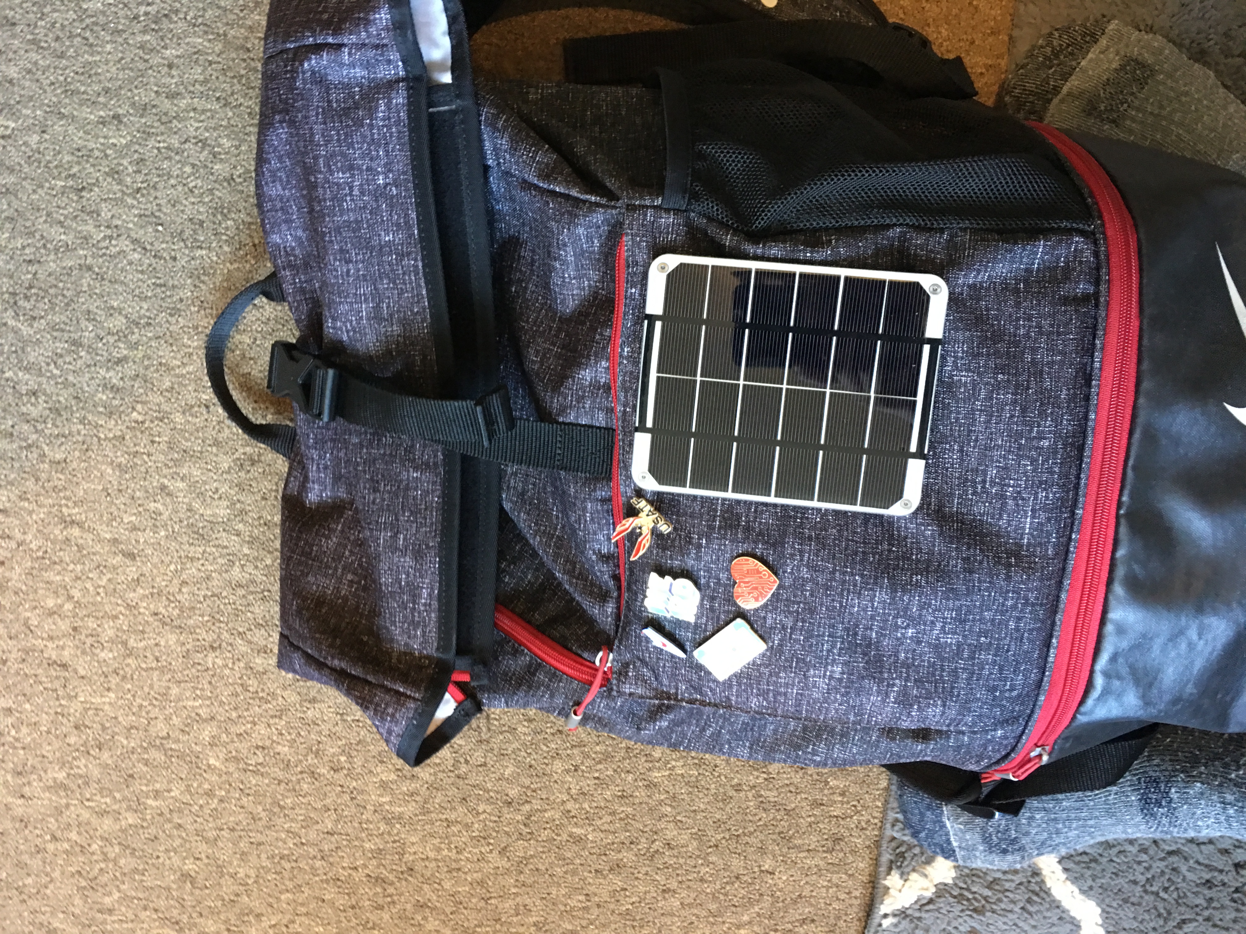
The whole circuit goes from solar panel to a USB/DC/Lipo solar charger board. The Lipo load is connected to one 2200Mah Lipo battery, but those things are typically at 3.7V- 4.50V, and I wanted it to be useable to either charge a phone directly or another, larger battery in tandem. I used the Adafruit Powerboost to kick the voltage up enough to adequately charge the phone.
Now a big battery lives in my backpack and is charged as the days go on by sunlight. Since I usually only use the big battery less than once a week, this a pretty nice setup, almost guaranteeing I’lll have charge when I need it!
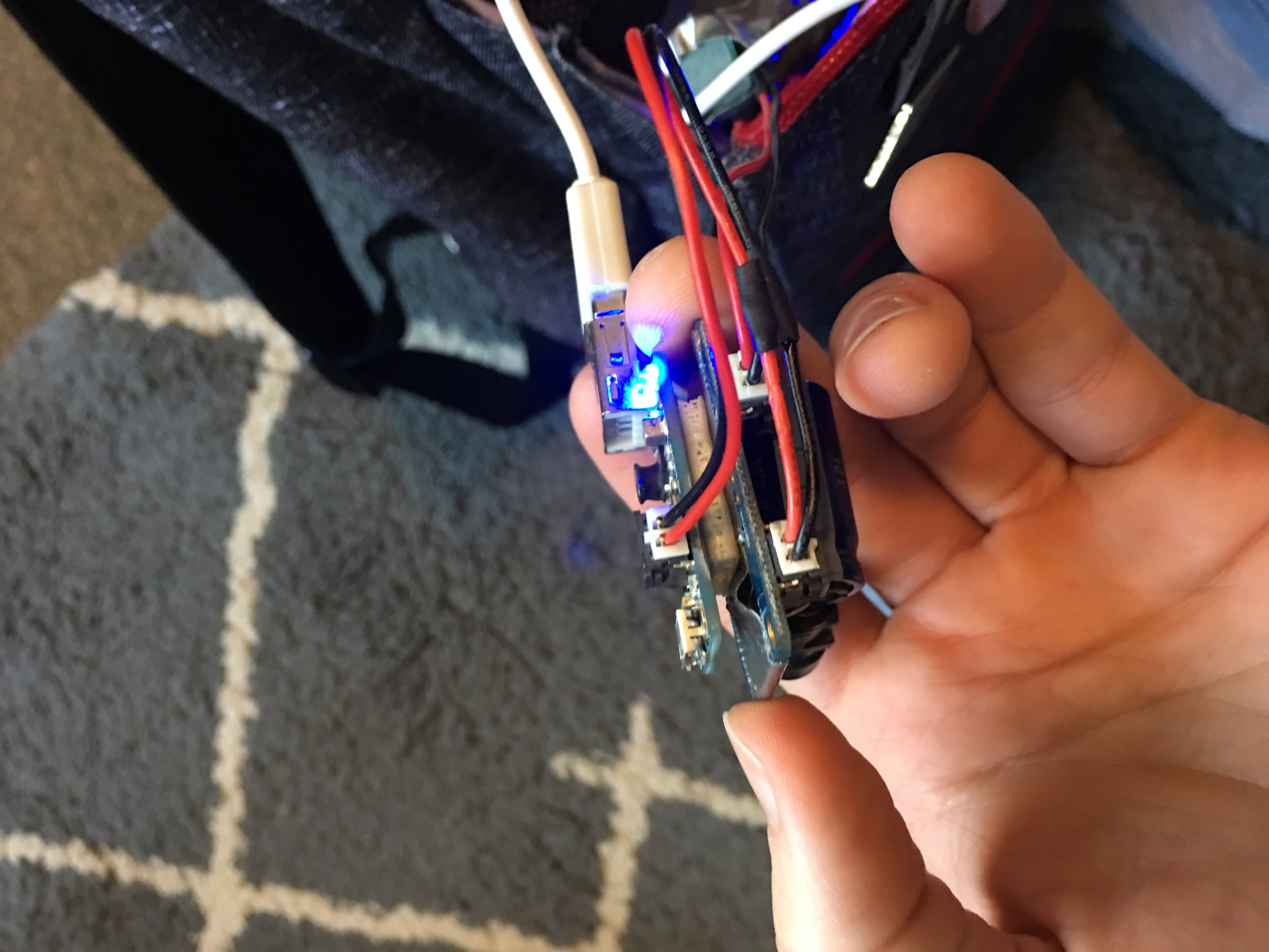
Yes duct tape was used liberally in the creation of this project.
The Avengers are sweeping across theaters everywhere these days, and ever since Iron Man came out, I knew who I wanted to be. JARVIS, Tony Stark’s personal assistant, keeps everything running smoothly for him. He responds to audio cues, much like a Google Home, or Alexa, (Or homepod at this point). I wanted to make one of these guys and use it as a long work in progress.
I had built a GroupMe chatbot a while ago using Machine Learning, natural language analysis, and reverse naive Bayesian filtering. It was actually pretty helpful! The bot could get me bus times and calendar events, as well as respond to input in whatever fashion I desired.
I thought I’d marry this bot to the Google AIY kit, and then give the thing eyes. Essentially I want a sassy version of Tony Stark’s camera buddy. This guy: (I think his name is DUMB_E?)

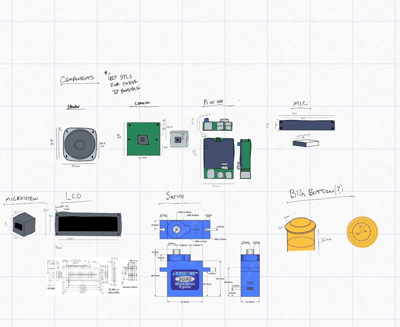
Anyways, the cardboard kit that came with AIY just wasn’t good enough, so I thought I’d print my own enclosure.
I decided on the name “Ava” for Autonomous Vocal Assistant. Clean and catchy.
Used the Concepts app again to gather measurements, take notes, and draft ideas.
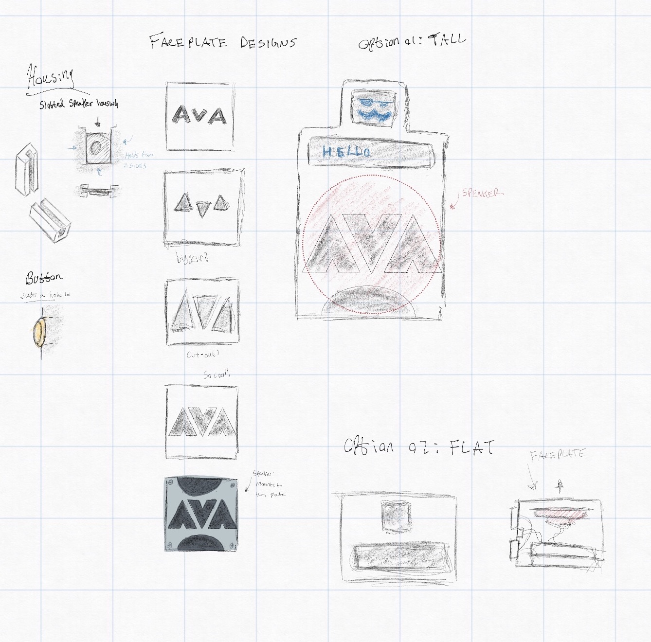
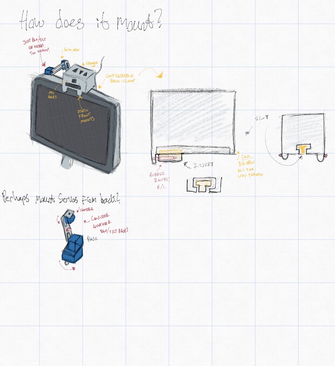
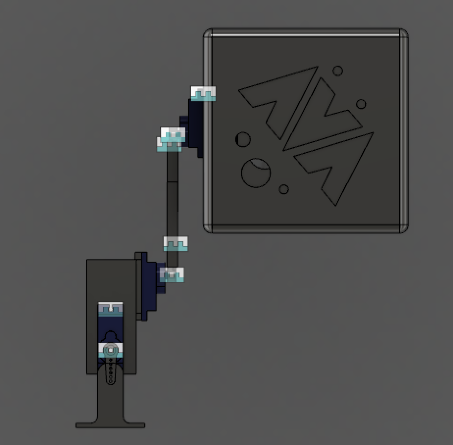
Once I settled on something I moved into Fusion 360:
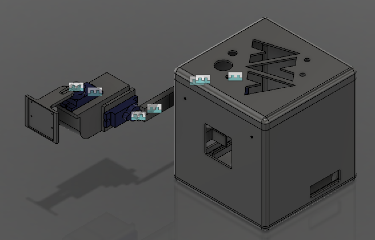
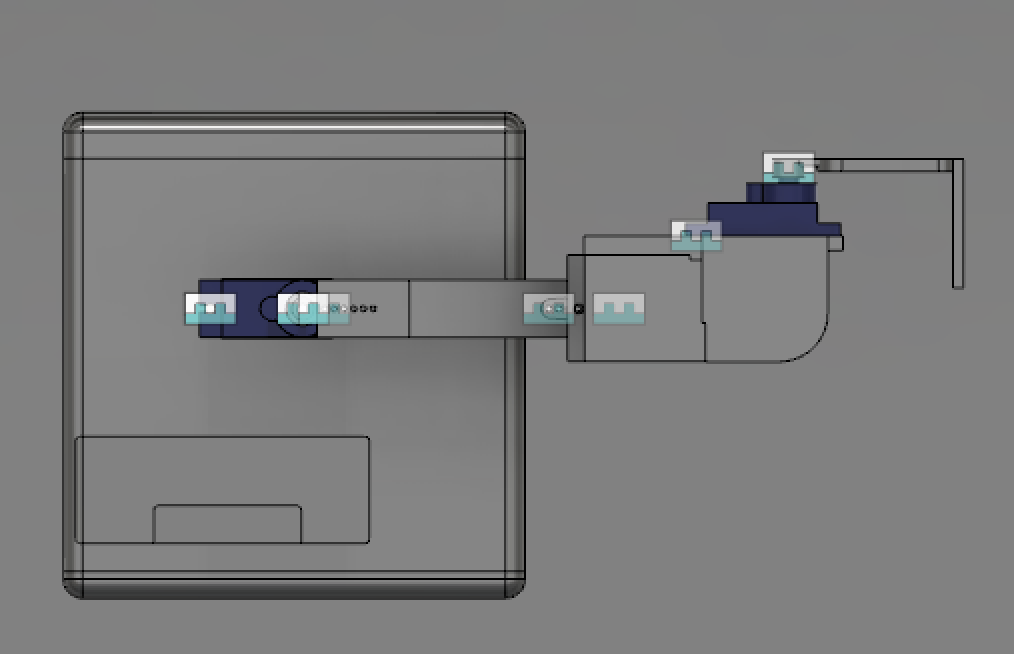
I actually printed these pieces at the local library!
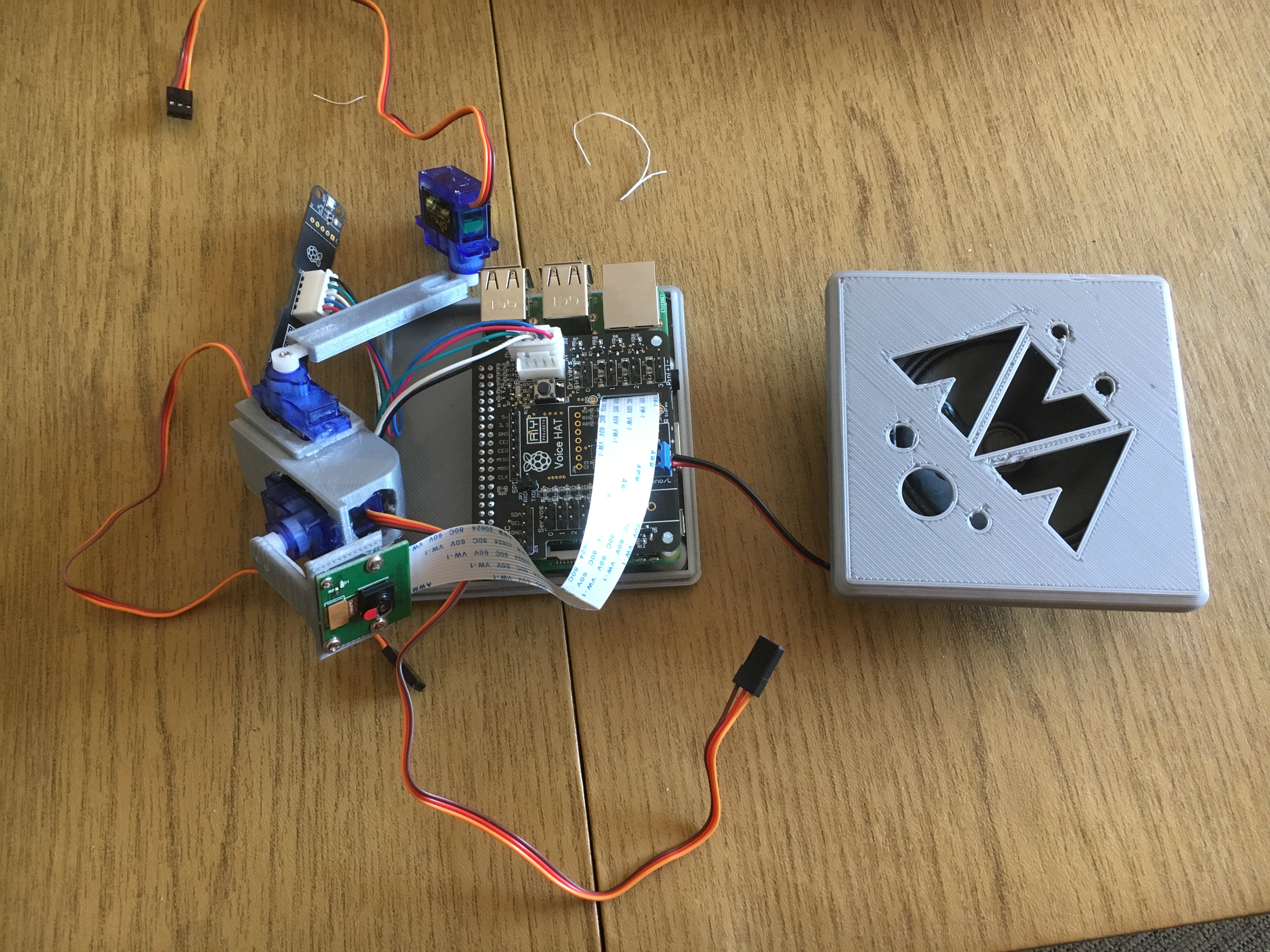
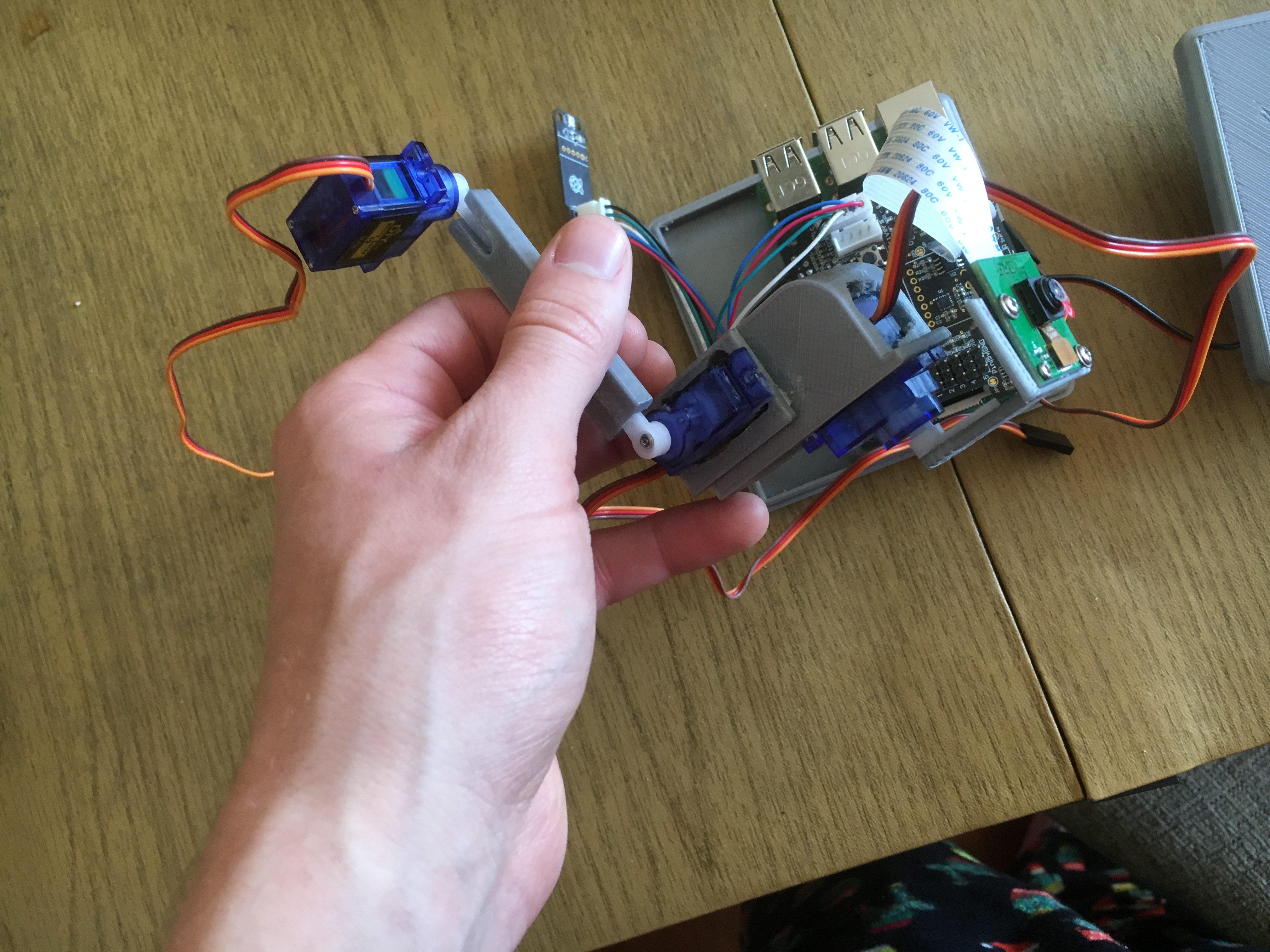
I got everything done but the body. They emailed me all in a tizzy that it was ‘giving them problems’ and I didn’t understand what they meant. Then they sent me this picture:
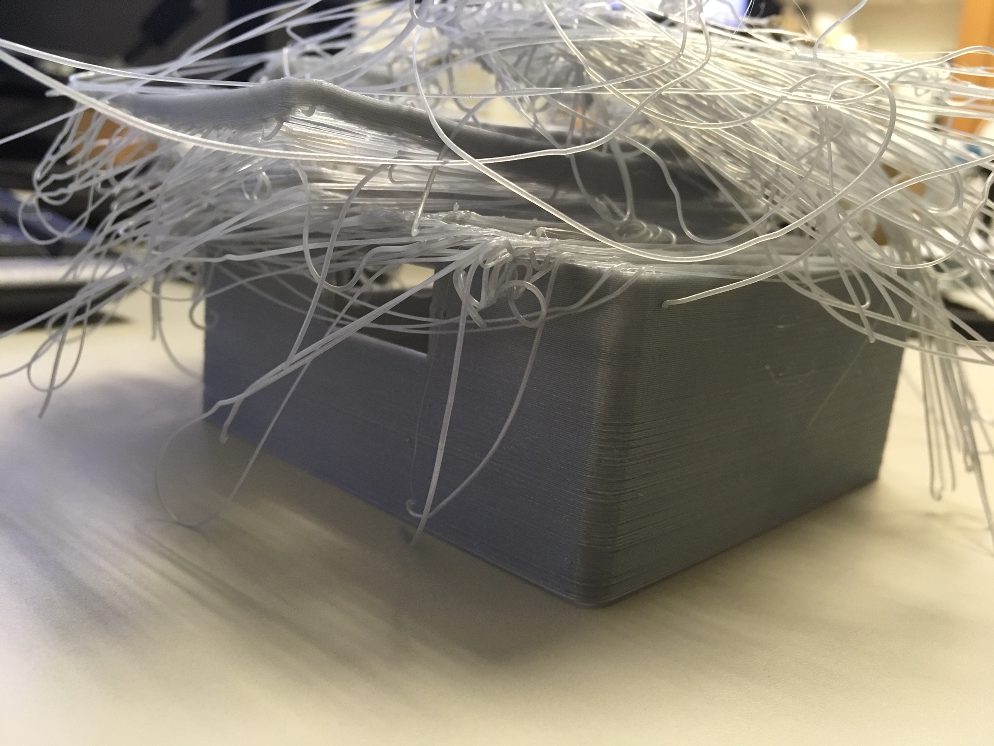
So Idk what I’m gonna do about that. Once I have the enclosure complete, though, I’ll get to work giving it a personality and skillset.
I definitely think an annoying alarm clock would be great, or for the bot to tell me when the bus is getting close, among other things. More to come!
hackeryWe had a little time to prepare for Mother’s Day, since finals ended a few weeks ago. Instead of buying something, we decided to make something for Mom. I actually originally saw this on a DIY instragram account, and I knew it would be perfect for her. We have a canopy on the back porch, which makes watching country sunsets a joy. Sometimes we light a lot of candles and drink tea in the semi-darkness. I wanted a way to make the whole fire thing less messy and more presentable, and so we decided to build a tabletop fireplace!
First, we took measurements of the table and the sterno cannisters and I set up the whole thing in Fusion 360, making sure everything would fit.
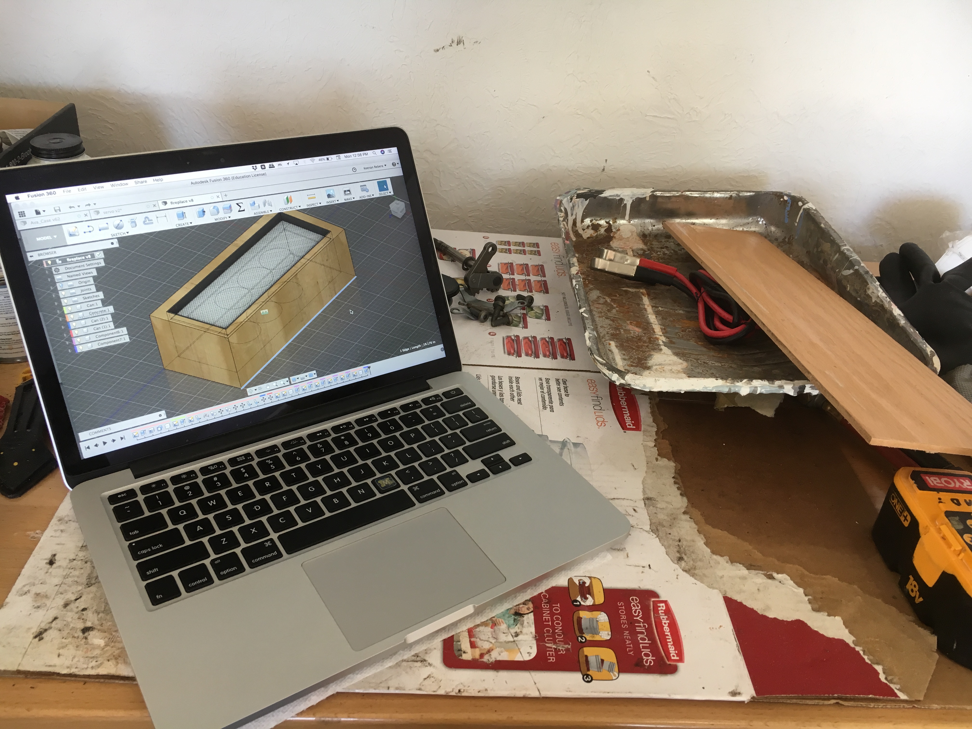
After this, we built and inner and outer wood frame and poured the concrete. After two days of drying, everything seemed fine, but we realized that upon rubbing the surface of the block, the concrete would just fall off. It hadn’t dried properly. Dad had decided to cut a corner and pick a different kind of concrete. This was not a good decision. Don’t cut corners! Do it right the first time. We had to cover the conrete in cement adhesive and then sponge on an outer layer of touch-up cement.
After this, we applied the backsplash and maple frame on the bottom. Then we grinded down some angle brackets and joined it with wire mesh. Lastly the fire-glass went in.


I’m pretty satisfied with how this turned out! I think Mom is too.
Good work, team, and Happy Mother’s Day.

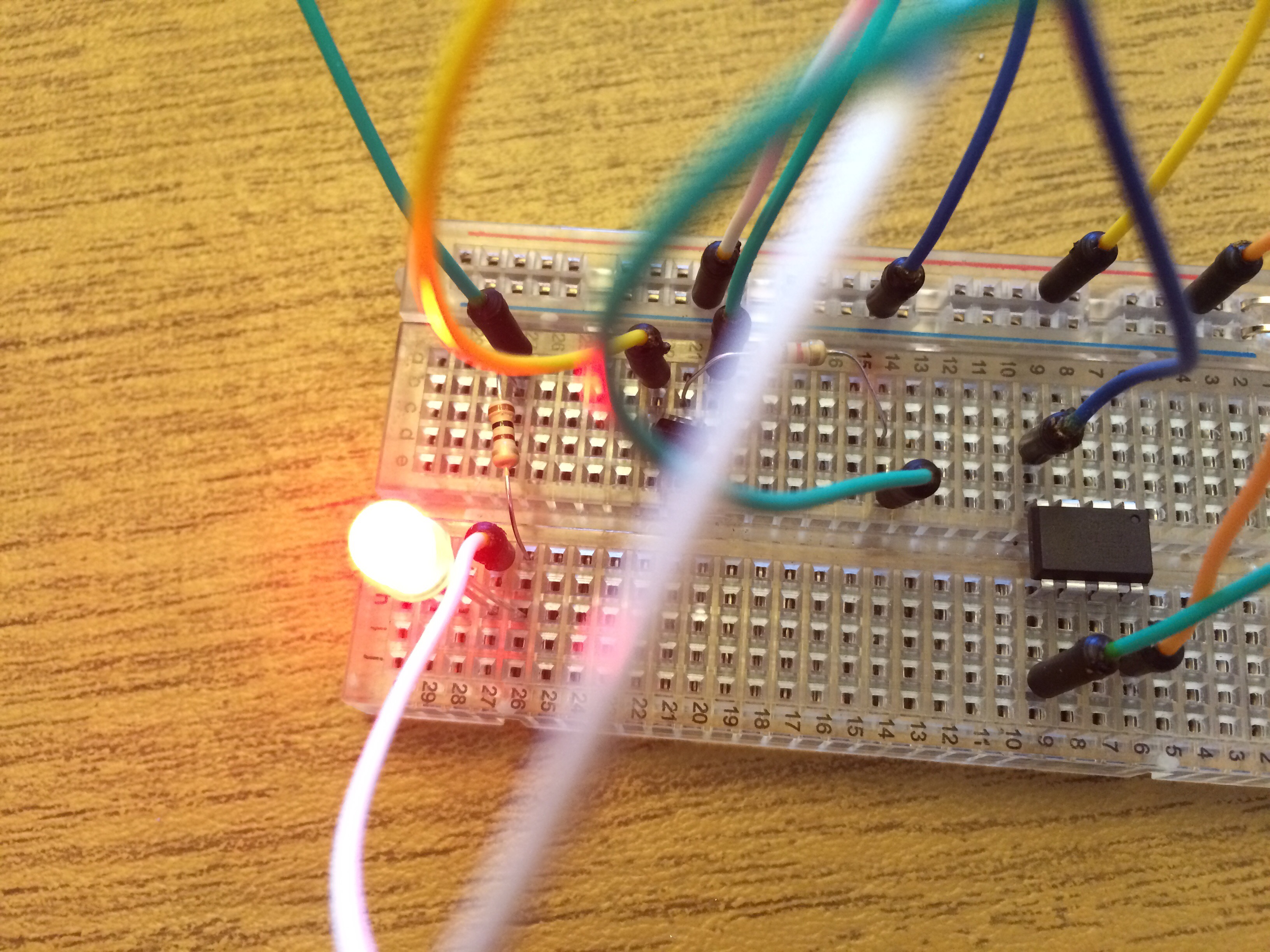
I finally got the whole rainbow to work! I ended up using an ATTINY85, as it had the perfect number of PWM pins for the application. I’m considering upgrading to an ESP later so I can control the thing over wifi like it was originally meant to be controlled.
Firstly, the wall wart itself is 12V and the LED’s will draw way too many amps to run the power through the attiny. My solution here was actually to rip the 5V regulator out of one of those cheap-o cigarette-outlet chargers that I found, broken, in my girlfriend’s car. The regulator, however worked fine. Thank you, charger, for donating your body to science.
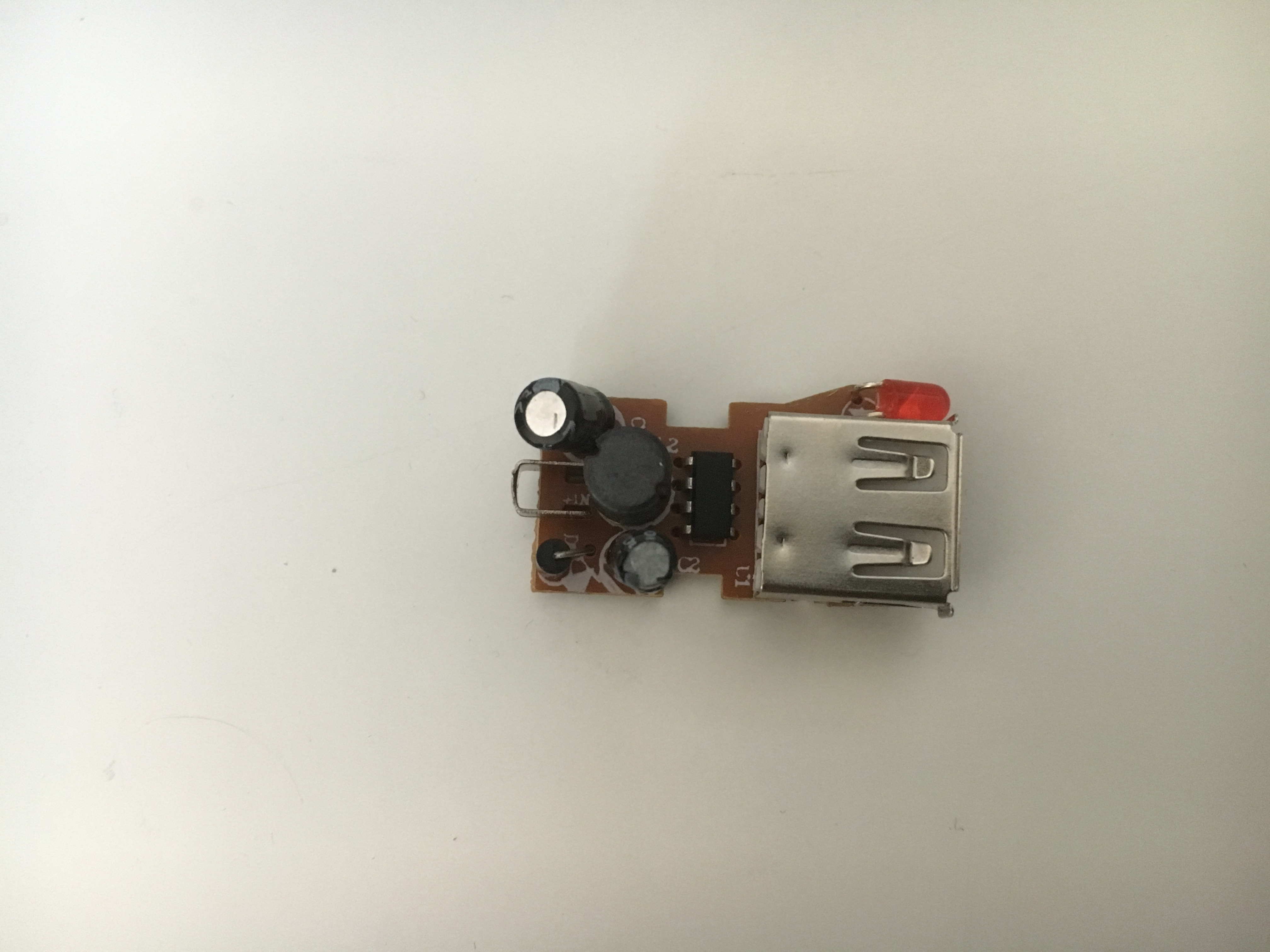
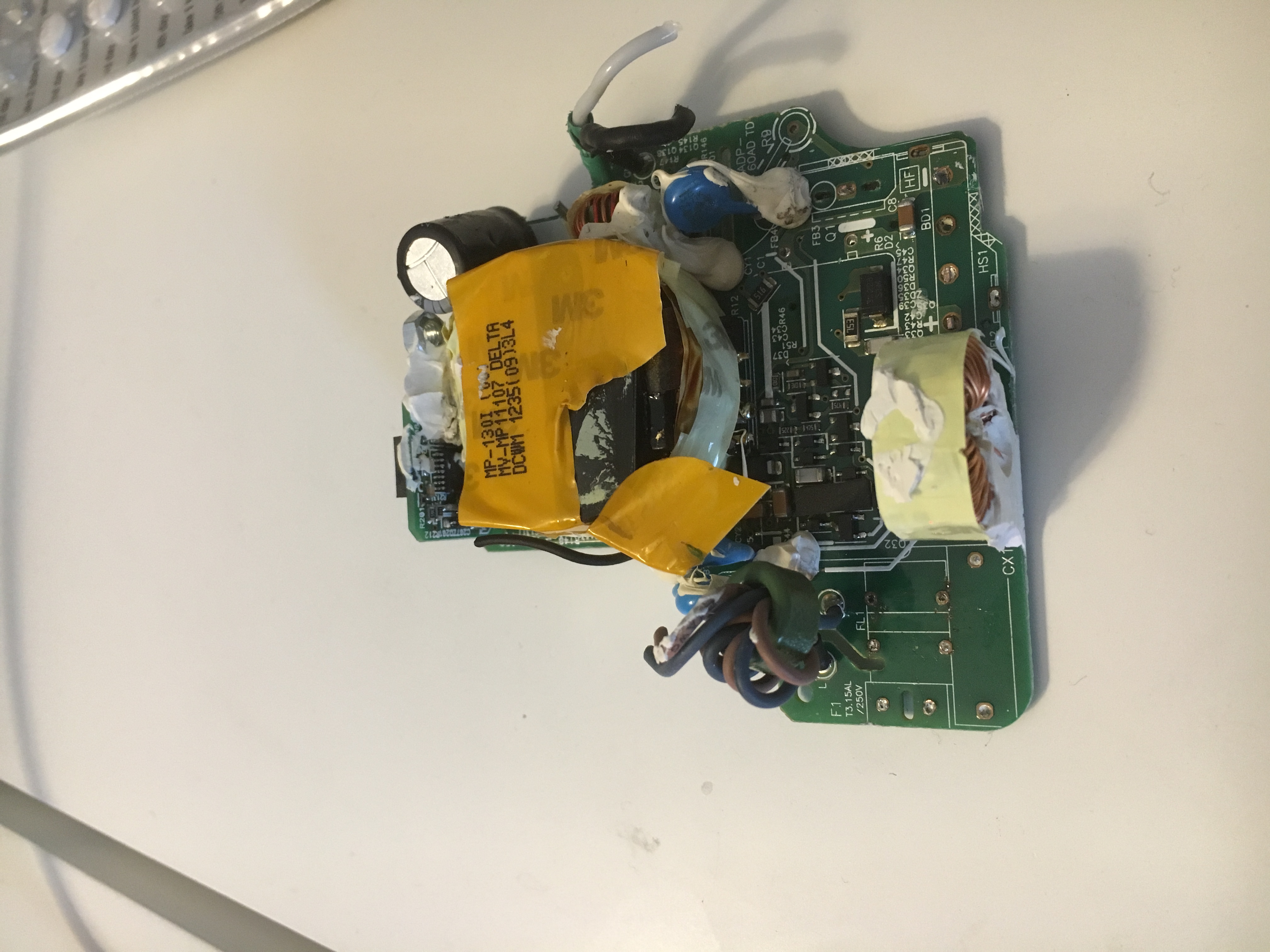
Then I needed two more N-Channel power MOSFETS in order to safely drive the voltage on the G and B pins independently. These came from an old, broken macbook charger:
After that, I expertly drew a little schematic to work off of. Very professional stuff.
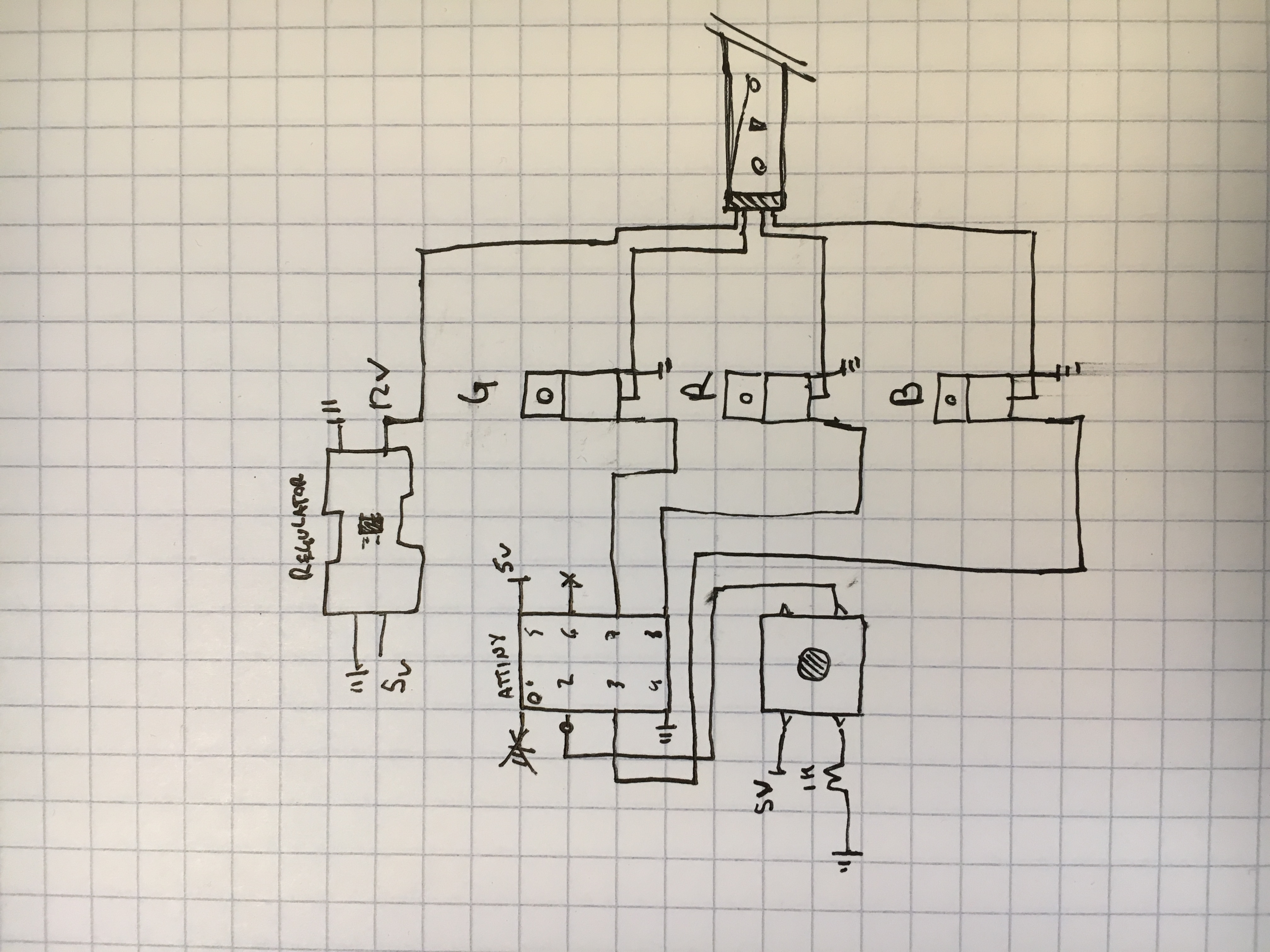
And finally, here is the completed breaboard and a gif of the operation. Success never felt so colorful. I’ll be excited to put this in my room when I switch houses in the fall!


So since it’s the end of the semester and all, kids are moving out of the dorms and leaving all of their weird things behind. In one night we found two microwaves, four car batteries, a Keurig, several lamps, and some kind of wifi-connected RGB LED reel with a power unit. Upon closer inspection, the reson they were thrown out is becase the unit didn’t have a control module. The power unit just ended in a barrel jack and the strip had a 4-wire connector. What a better candidate for some hackery?
After splicing the power cable, I still only had two wires- power and ground. After verifying that it was still spitting out 12V with my multimeter, I soldered some header pins onto the ends of the wires and tested the terminals on the LED strip. None of the myriad configurations worked. Then I tried joining all of the misc wires to power, then to ground. That didn’t work either.
I was about to give up when I decided to pull back the heatshrink tubing covering the LED connection. The pins were labeled! +12v, R, G, B. I hadn’t noticed up until this point that these could’ve been RGB strips.
One high-wattage N-channel MOSFET later, and the thing is up and running. I used the +12V on the Vin terminal of my old arduino and just sent a PWM slow pulse through to the MOSFET, then paired R, G, and B to the drain.
The MOSFET in question is a 2KS2645. It was just a random piece of silicon I had in a junk bin. I think it was from a printer-scanner I tore apart my senior year of high school. The only reason I picked it is because it had a heatsink, and the datasheet showed it could more than handle the strip (50W!)
I’ll probably go and find some more somewhere so that I can control all three channels except for one. I’m moving out right now, but this will be a nice addition to the room I’ll move into come fall.
More updates to come, I’m sure!
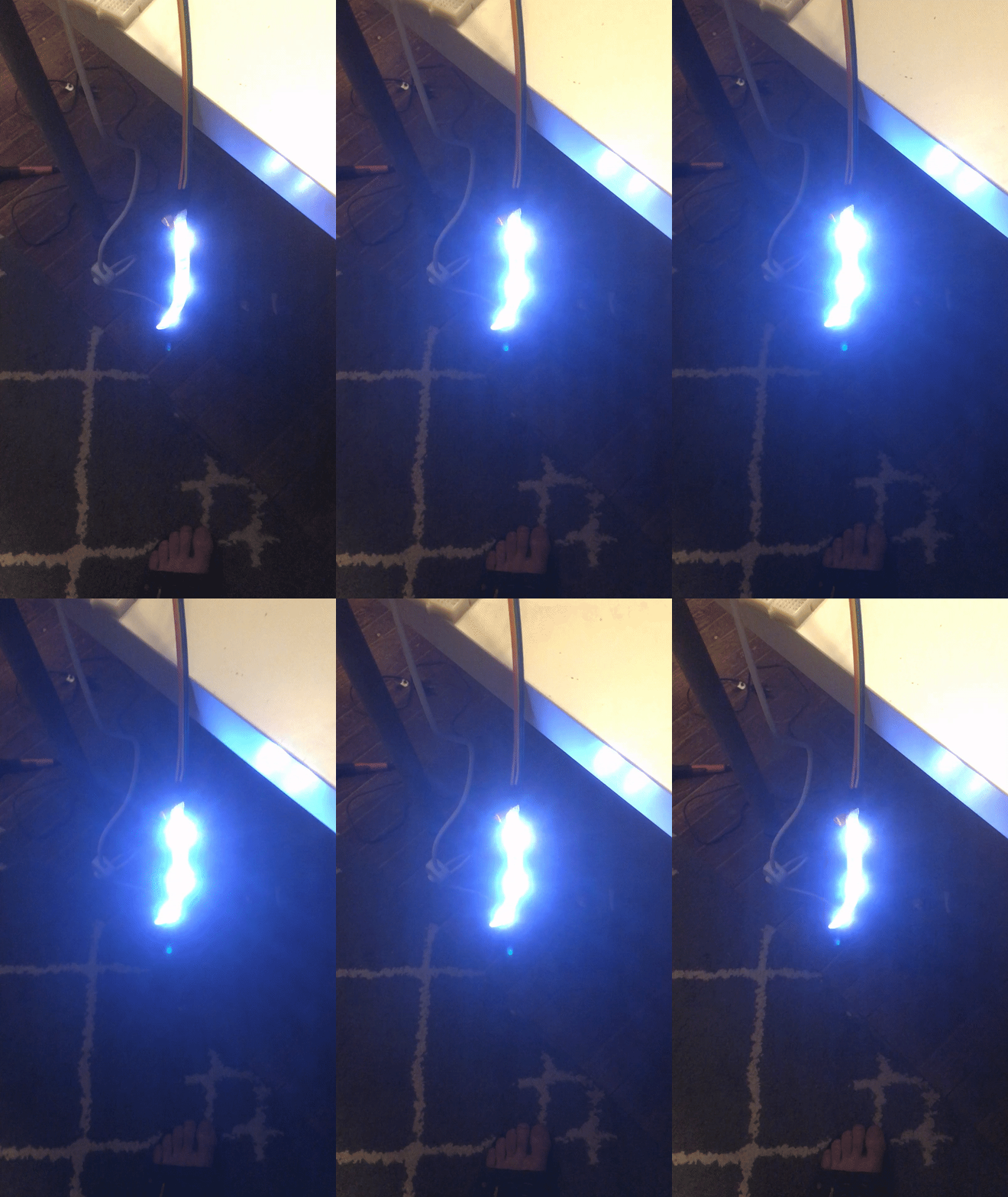
YEET! I just finished my last exam and am officially a senior! Hopefully I can finally start making posts to this blog. See you all soon!
So I owe my friend a gift for his birthday. Years ago, I promised him I would build one of his zanier inventions: A hat that always points north. However, due to school, injury, and various setbacks / distractions, I never really built it. Then I ordered the parts but got the wrong magnetometer, and then the microcontroller I was going to use actually ended up being bricked. However, I persevered, and might actually get the thing done this time.
I had to take into consideration a couple things: The type of servo, the configuration upon the head, and how to best avoid the thing pulling hair out of the user’s scalp. I did a lot of my design work in the ‘Concepts’ app for the iPad pro. Great little tool. Very fun to work with.
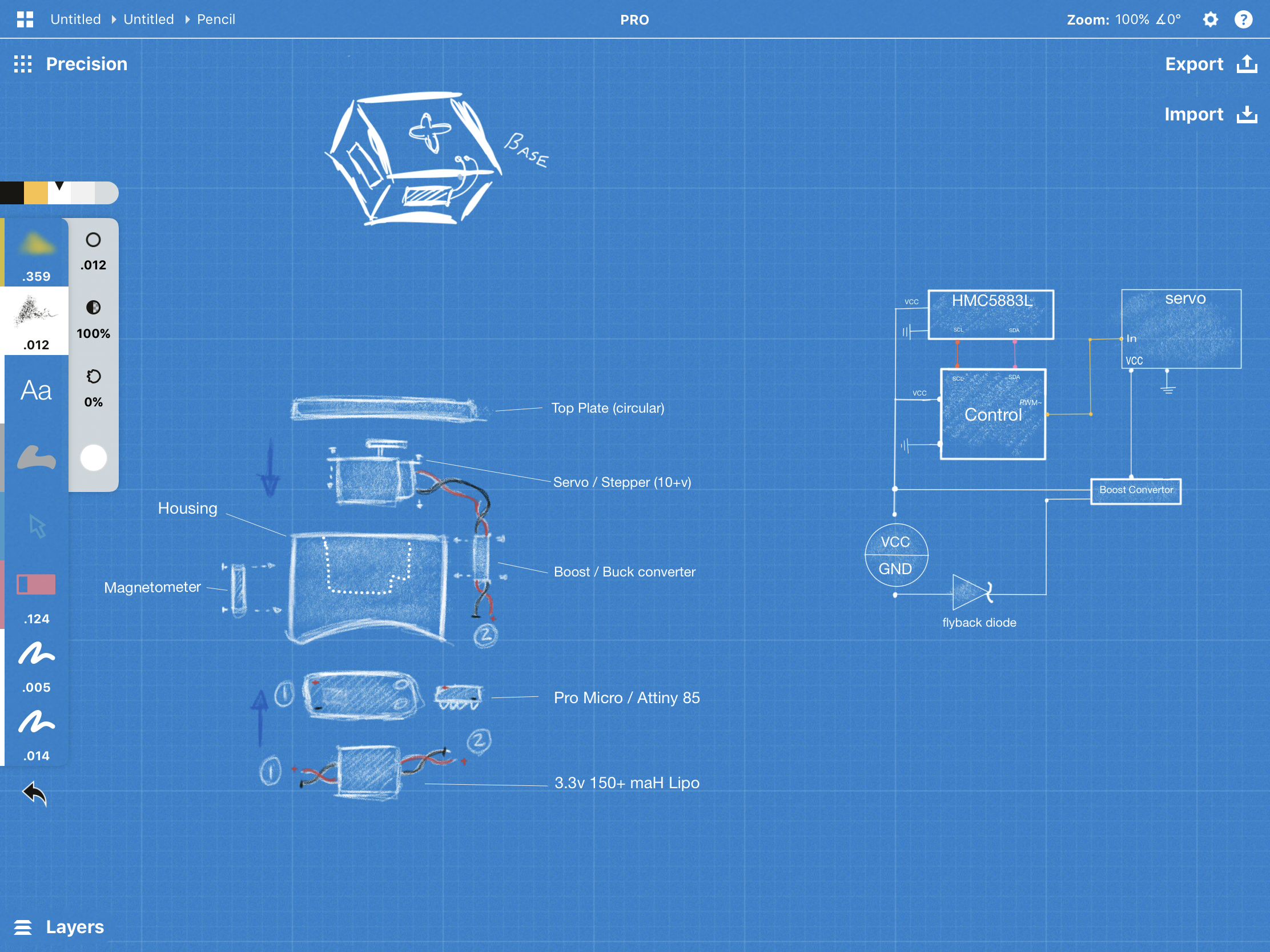

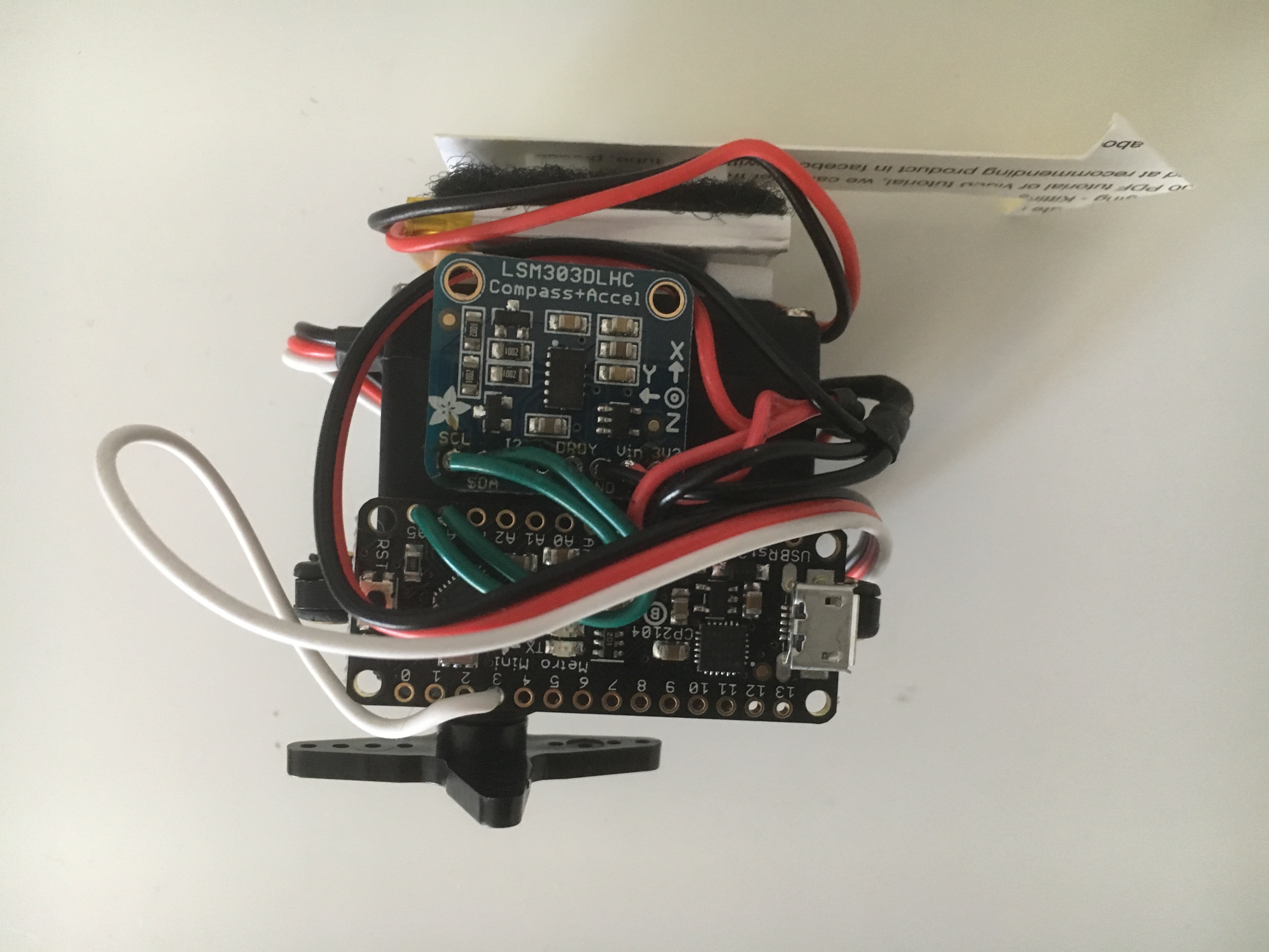
Building the thing proved harder than expected. Mounting all the pieces on the motor was a little difficult, and testing the magnetometer sensor was hard until I built a janky prototype for some quicker testing.
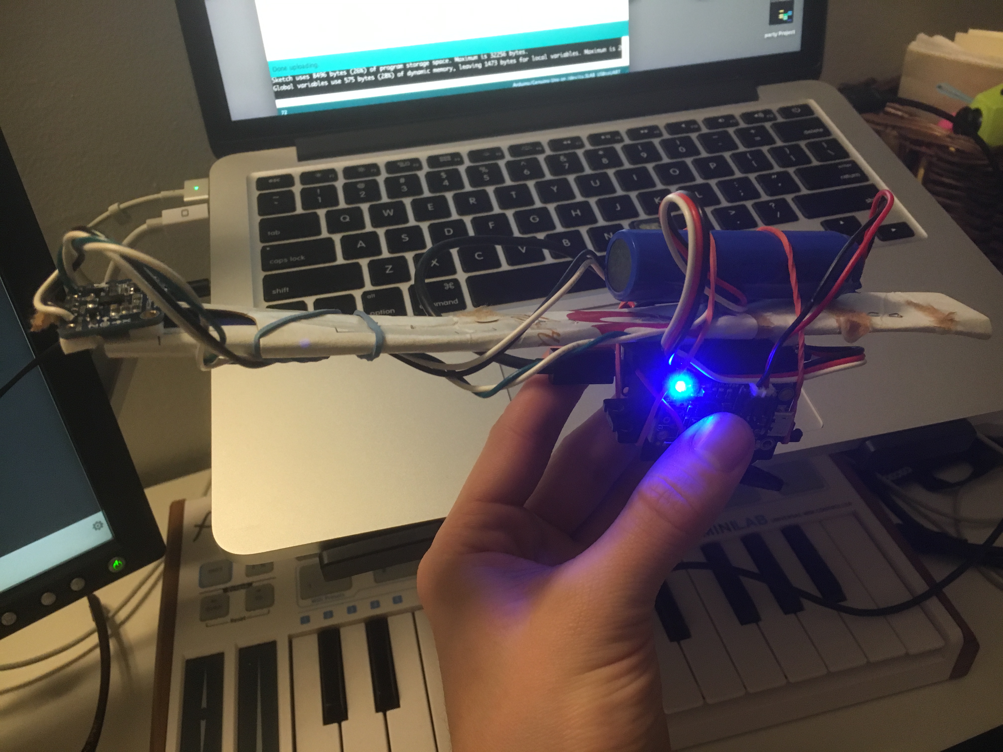
I had a great time testing this one, and actually implemented my own PID control for the thing, so it behaves quite accurately and doesn’t overshoot like it did at the beginning of the process. Perhaps PID is a little overkill, but honestly this gu deserves the best we engineers have to offer.
I still have to solder in a few switches and complete the enclosure, but it’s done for the most part! Look out, world. Perhaps you’ll see it on Shark Tank sometime soon lol

Still in the enclosure design phase! I think I’ve printed like 6 or 7 prototypes at this point. Really struggling with warping, since I don’t always get the heated buildplate on the university printers. It’s first-come-first-serve there. On the bright side, the iPad Pro is great for annotating images in the design phase. Much better than a notebook.
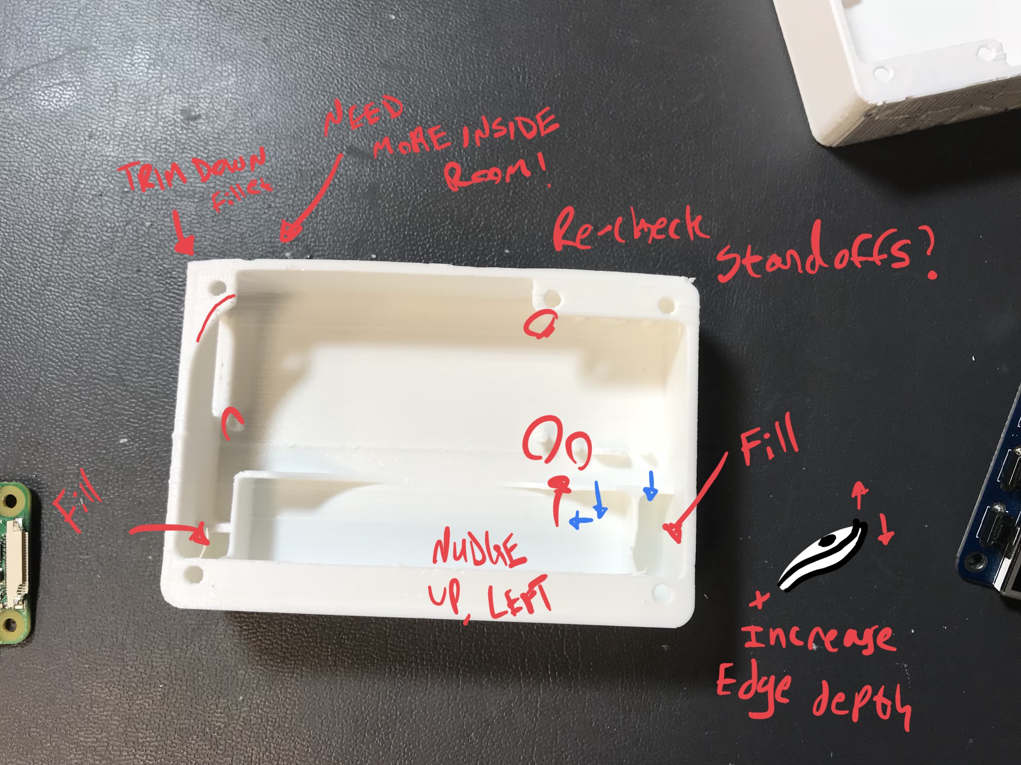
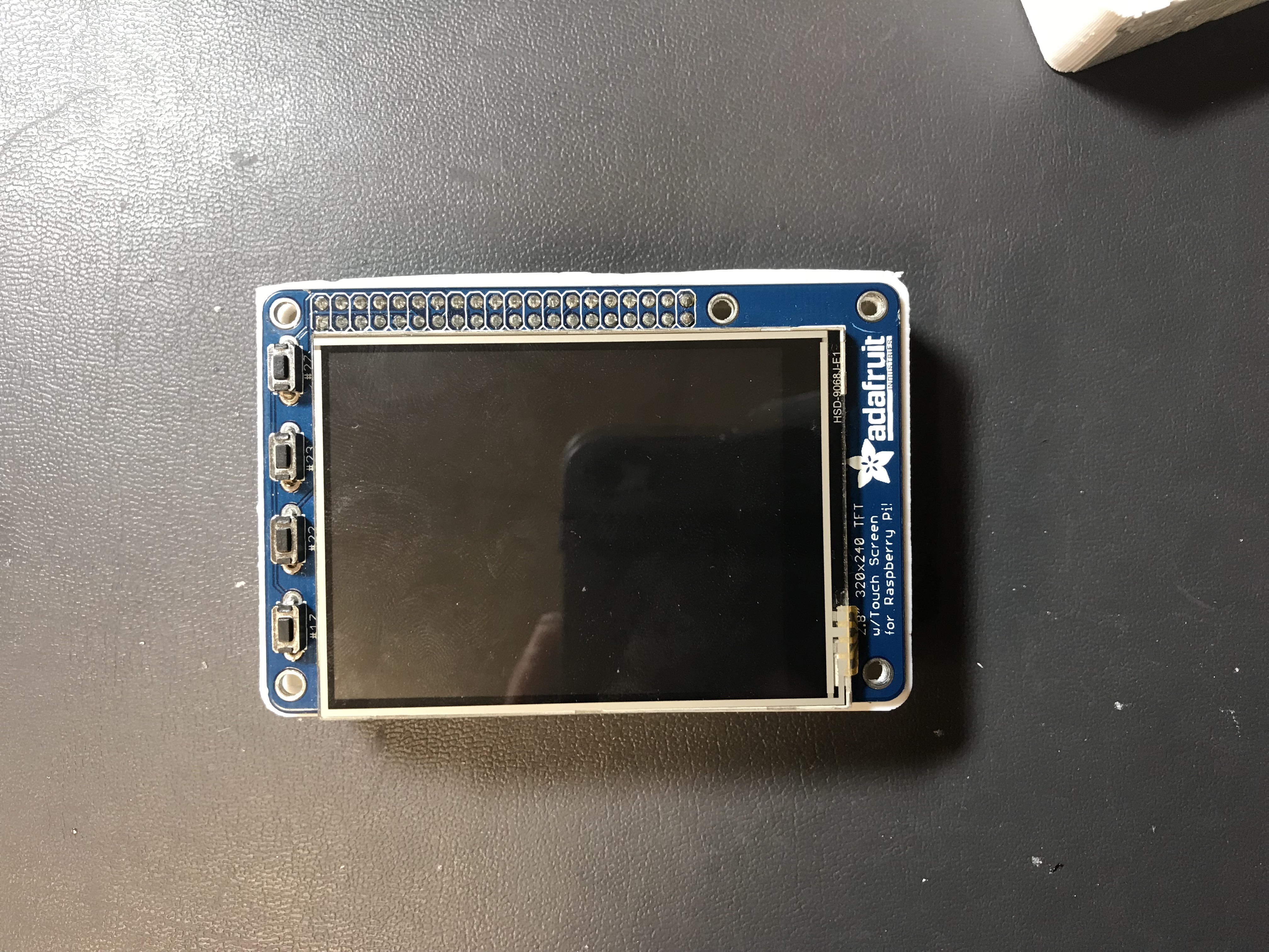
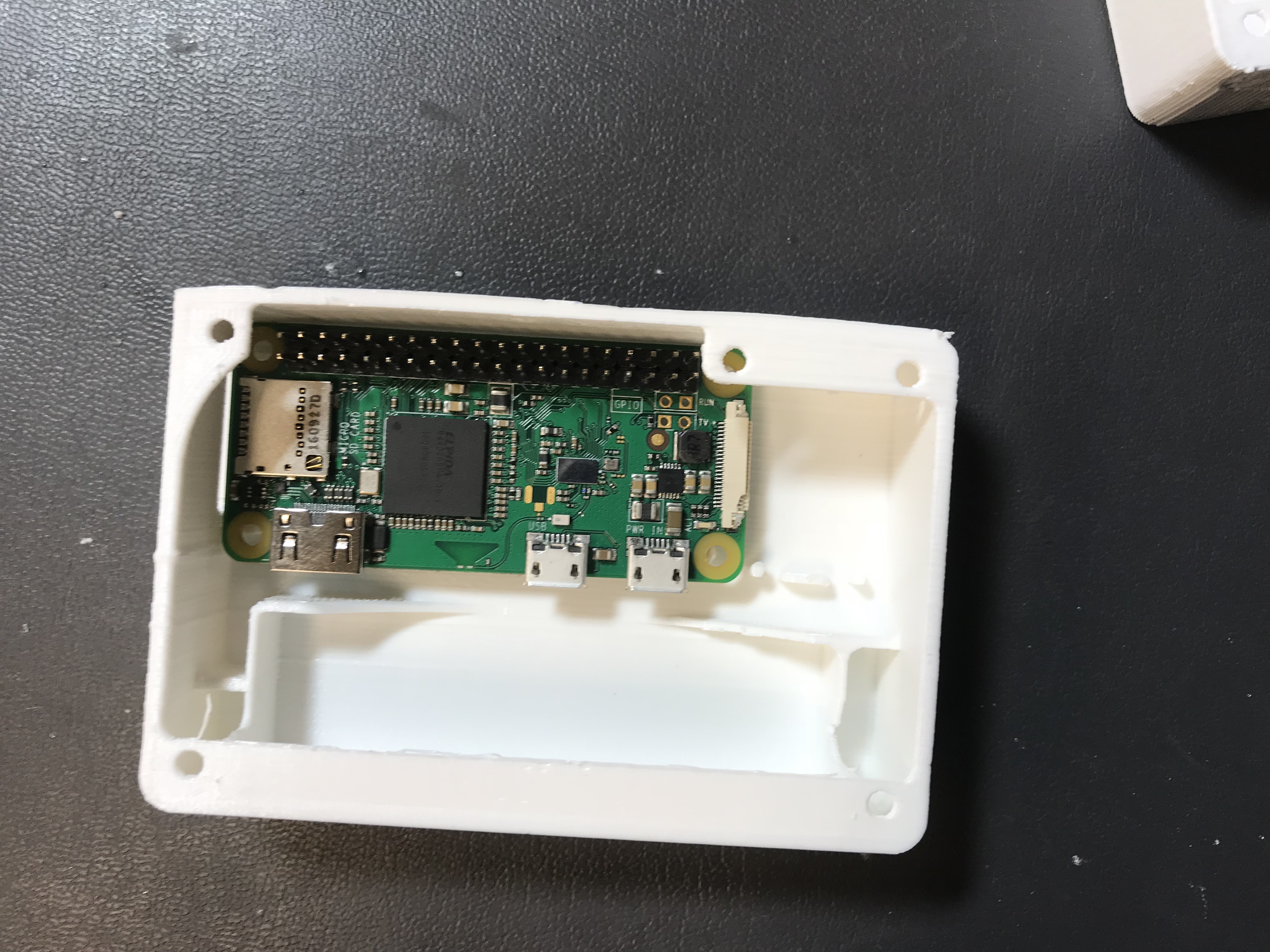
EDIT: I’ve actually totally updated this enclosure design after watching more Fusion 360 videos. More to come. It’s a lot, lot better now!
hackery
For my upcoming ArtsEngine Microgrant project, I’ve been featured on the Electrical and Computer Engineering website. I’ll be attaching a sensor array to the ‘Cube’ (Alamo) statue on campus. Using some physics and the parallel axis theorem I’ll be doing my best to compute realtime velocities. Hopefully the pi-zero can keep up.
Here’s the link to the full article.
Here’s a small preview:
hackery cube-projectCE junior Keenan Rebera wants to make the Michigan Union’s famous Cube sculpture even more interesting with the power of technology. The spinning metal art installation nestled on central campus draws a lot of curious eyes, but Rebera thinks he can take the experience to the next level.
Rebera has designed a small sensor array and display device that attaches magnetically to the Cube. When active, it can detect the velocity of the Cube when a person spins it and generate any number of fun factoids to show off. How fast did you just spin this thing? How many times has it been spun today? If The Cube were a generator, how much power would it be producing right now?
Well, I had a solid half-hour before practice and decided to build a twitterbot.
(You can follow him at @trumpybot)
I had him set up on a crontab but then decided to make my own little menu system so I could cycle through the poorer generated tweets.
(Following this tutorial closely.
Essentially, the code takes 20 or so trump-isms, goes through some adjective and noun repositories on GitHub, and then creates a madlib with some random generation, spitting out interesting results.
From there, tweepy handles the rest. Doing this in Python made things really easy!
My tiny python menu system:

And the end result:

I started by shopping a case out of wood, sanding some of the rougher edges into rounded sides, and carving in an indent to mount the screen. Ended up using those little picture frame clasps to secure the screen.
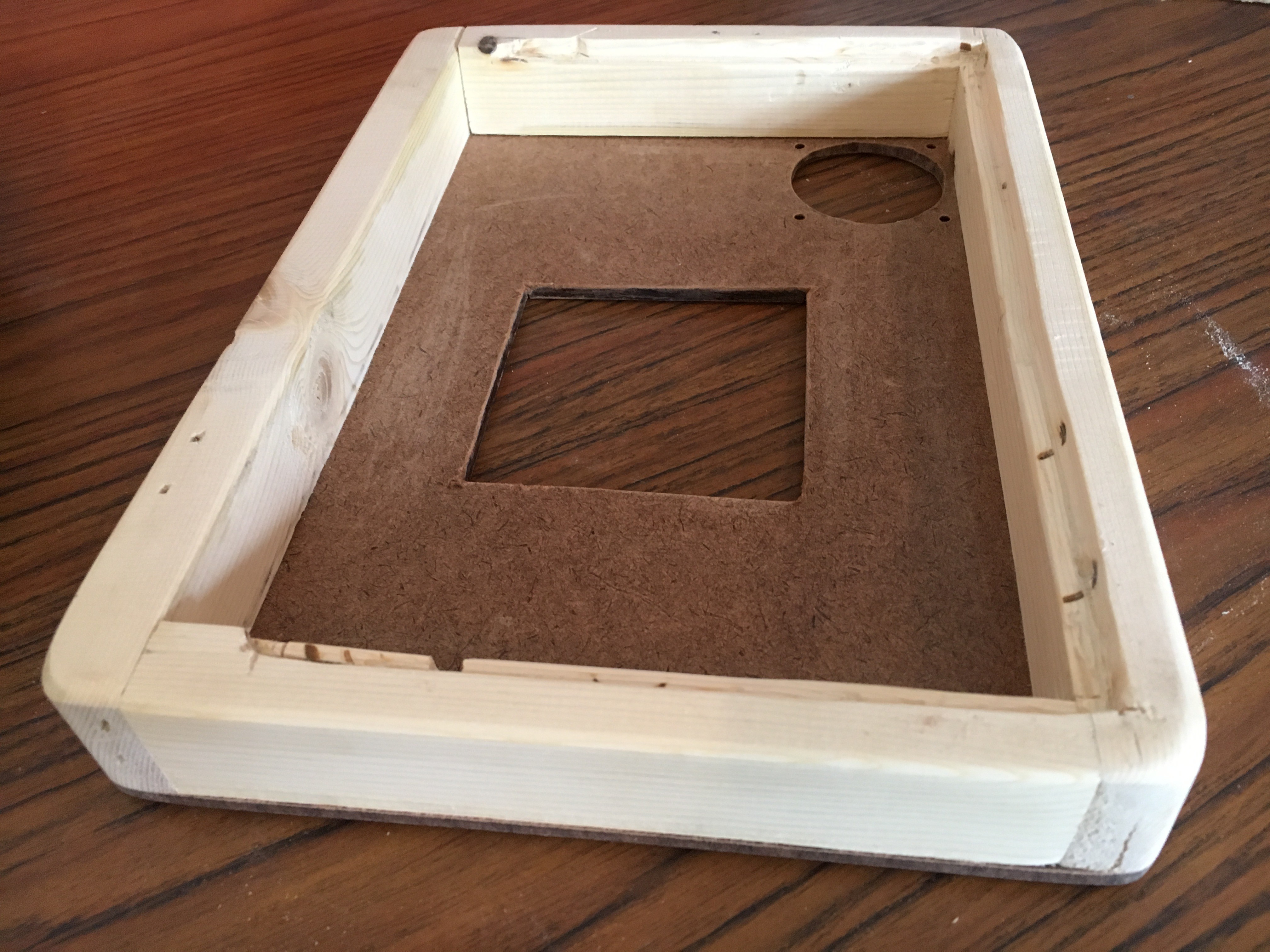
From there I spray painted the body and cut out a stencil for some sticker paper and sprayed down a piece of plexiglass that I sanded with fine sand paper for diffusion.
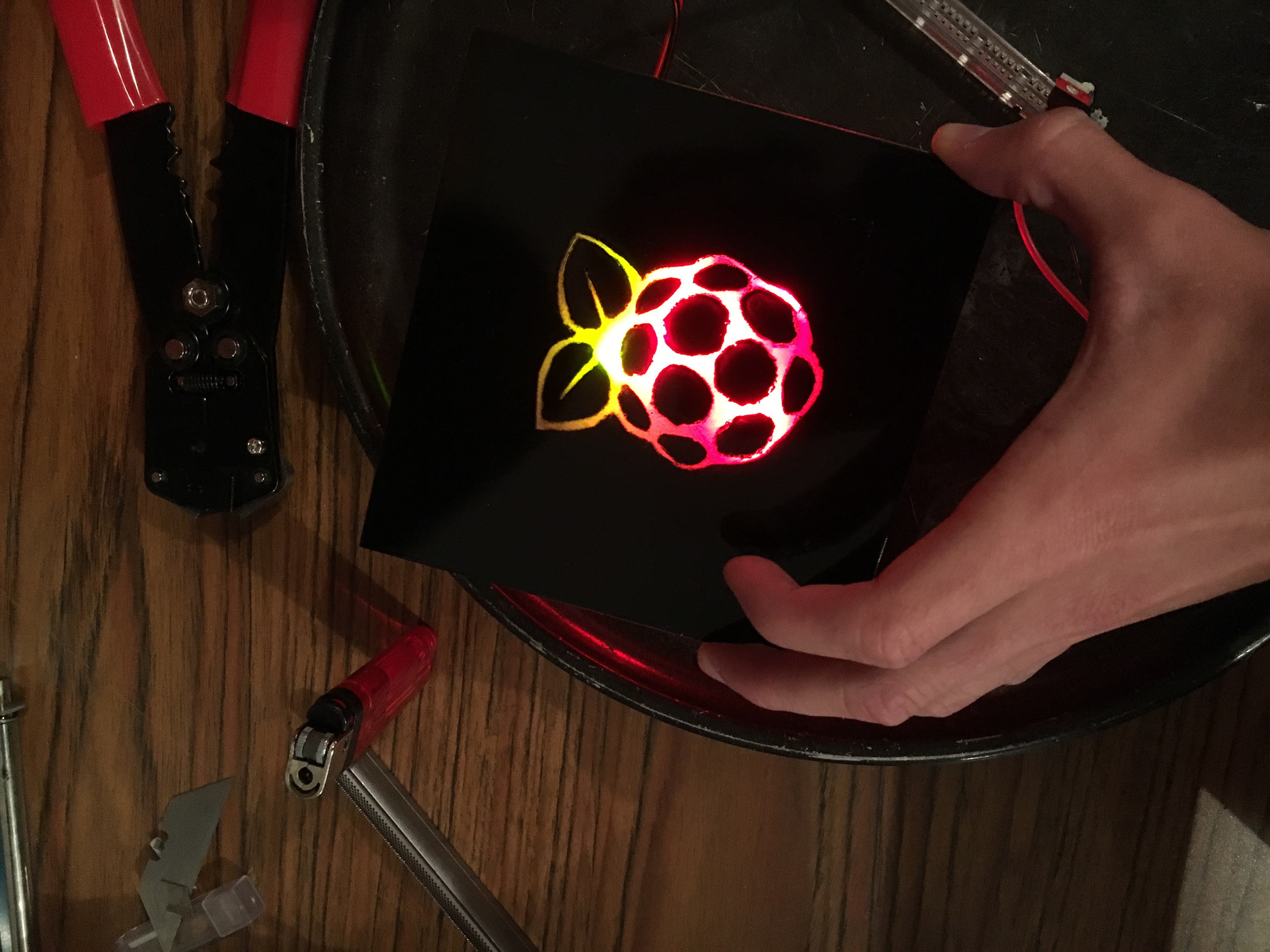
I was able to tie all the components together and have a generally operational setup:
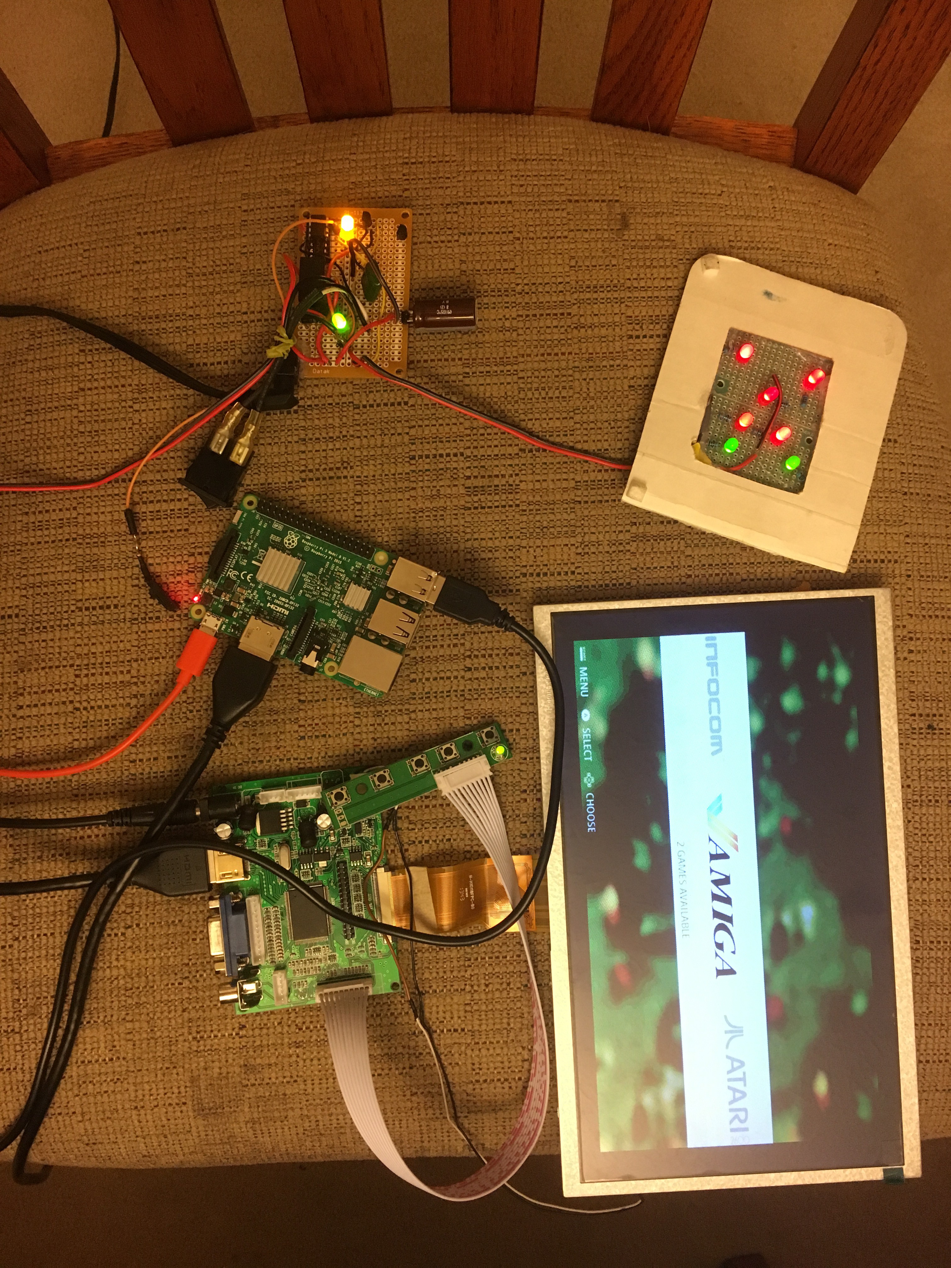
Then I shoved it all into the case, added a kickstand and clasps to secure the screen:

So I started to test the thing, and I realized that there was a colored square in the upper right corner of the screen when running the device. I read that this was a sign of low power. I went and designed another case in Sketchup to see if I could manage some better spacing and heat dissipation:


And that was actually pretty fun because I have minimal experience in CAD programs. Didn’t struggle too much with this though because I have hefty experience in Blender3D.
So I redid the power circuit to see if my switching mechanism was weird and struggled alot with the new design. I kept having odd issues, and eventually consulted a forum. We settled on this solution:

I was recently exploring a mechanic in which the player doesn’t directly control the motion of the player object in the game. Instead, the player object moves along a consistent sine-wave and the player is given the ability to adjust the amplitude and period of this wave, effectively creating an interesting control scheme that will take a little time to master:
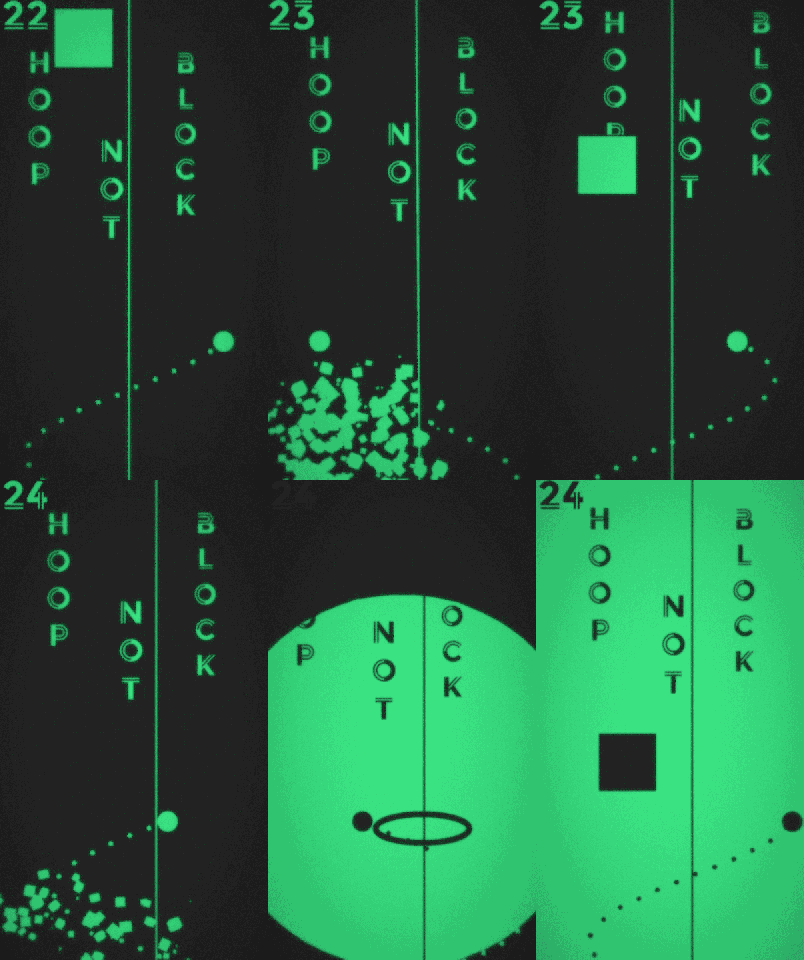
I love messing with alternate control algorithms, but they aren’t as easy to implement as you-push-up-I-go-up schemes. The challenge here is getting the sine wave to adjust itself in relation to the player only. To modify the amplitude or period at any one time is to change the structure of the motion and therefore the player position. This leads to predictable but strange mechanics that don’t make sense in the form of a game. This algorithm, admittedly, took me two weeks to figure out, and in the end it was solved by five lines of algebra and a dash of common sense.
Trying to test different algorithms inside of the player control code was messy, and soon debug variables and values were running amuck in the previously clean and workable code. If you want to play around, build a test scene! Put it in its own folder and keep it all together. Have a riot.
If there’s something you’re going to be changing a lot, please just put it in a function. I found myself switch around variables in three different places in my test code and it got frustrating and confusing quickly. Soon the numbers you predict don’t appear because you forget to change it in multiple places. Put it. In. A. Function.
I tried to use smart ordering to make everything work out nicely, but then I realized that I needed to see where the player is versus where the player might be. They can’t be the same thing, otherwise nothing would change. I ended up hacking out some functions that dealt with their own local variables and predicted future motions. It’s a bit ugly, but I’m just happy it works. Elegance can be achieved in future iterations. Speaking of which…
Do it. Then do it again. Then get rid of the trash and do it again. Do this eight times over and you might get it. A step forward is a step forward, no matter how small. Rethink what you did and clean up as you go. It seems it takes me a few tries for me to even understand what I just typed out.
I might just be a spacial person, but I need to draw diagrams and write things down before I do anything of worth. No amount of intuition can best a well-drawn flow chart. Organize your thoughts, then write the code. Then organize that code. Then organize your thoughts on that code. Getting annoying yet? Good. Do it again.
Amplitude was solved by moving the graph over the amount the player character would be moved by the delta between the old amplitude and new amplitude. It was a classic case of move it, then move it backwards by that same amount.
Period was solved by about twenty attempts and then eventually a few lines of algebra. It became apparent after I realized I only had one variable to deal with.
Just happy I was finally able to nail it. Happy coding!
gamedevUsed some time this weekend to get a shield ready on some protoboard for the Arduino. It connects the correct pins for In-System Programming of an Atmel attiny avr. There are circuit diagrams all over the place for building these. I wanted a permanent and quick solution for programming and reprogramming.
In hindsight, a heartbeat and positive connection LED would be great for some feedback during programming. An exposed reset button extension would be great too, as time-sync errors happen all the time with the Arduino-as-ISP. Luckily, solder isn’t permanent.
Most of what I worked off of came from the great information over at High-Low Tech:
The shield:
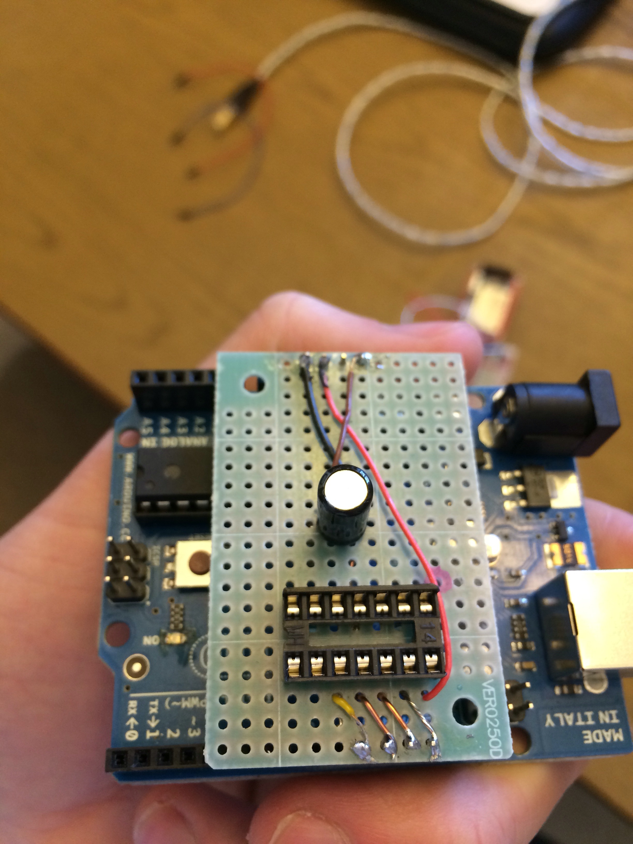
The programmed chip in action:
